Good Hand UK Ltd. These clamps are called C clamps because of their C-shaped frame but are otherwise often called G-clamps or G-cramps 1 because including the screw part they are shaped like an.

Assembly Drawing Of C Clamp Youtube
Clamps or G-clamps are typically made of steel or cast iron.

. Drawing is an assembly drawing of a group of related parts that form a part in a more complicated machine. 1 7 Jaw grip Steel 2 6 Screw rod MS. SOLIDWORKS 2017 STEP IGES Rendering July 26th 2019 Vice Grip Locking C-clamp.
Mainline Malleable C-Clamp wSet Screw Locknut rev. 4105 2 4 3 17981 C-CLAMP ASSEMBLY 7 1 NO. The DWG-version problem not valid file invalid file drawing not valid cannot open can be solved by the Tip 2869.
G Clamps Heavy Duty GH-M100. The following details the steps necessary to compute the stresses using FEA in SolidWorks. View C-Clamp Assembly Drawing 4of4 1pdf from ENGR 464 at San Francisco State University.
Prepare a complete set of working drawings with all of the detail drawings on one sheet and the assembly drawings and parts list on another sheet. A C-clamp or G-clamp is a type of clamp device typically used to hold a wood or metal workpiece and often used in but are not limited to carpentry and welding. See also block-statistics and the latest 100 blocks.
G Clamps Heavy Duty GH-M125. - 24 - 8 Movable Jaw CI. 21 TITLE C-CLAMP ASSEMBLY DRAWING Ø4.
View C-Clamp Assembly Drawing 2of4 1pdf from ENGR 464 at San Francisco State University. - 23 - 142 Machine vice Fig. STEP IGES Rendering August 28th 2019 C-Clamp 3 by Mitch Pomerantz.
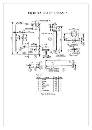
Problem 164 Working drawing metric PARTS LIST. HD Supply sm reserves the right to change or modify products without prior notification and is not responsible for the use of superseded or voided specification sheets. CAD Forum - tips tricks.
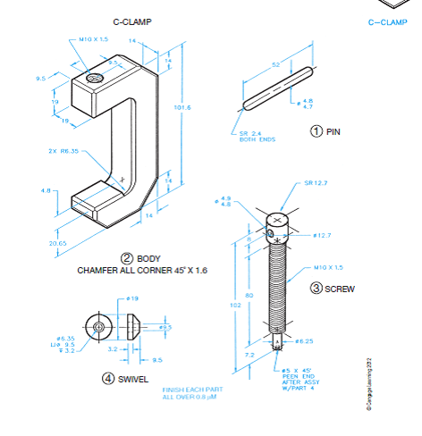
Weight HiVis Model CDF402 0-2 2 1 8 CDF402CHV CDF403 0-3 2 3 8 CDF403CHV CDF404 0-4 3 1 4 CDF404CHV CDF406 0-6 4 1 8 CDF406CHV CDF408 CDF408CHV CDF410 CDF410CHV. 16 QTY NAME PIN BODY SCREW SWIVEL SR 24 BOTH ENDS 102 72. Loads LBS Weights LBS Dimensions IN All dimensions listed are nominal.
By Ahmed ElPrince. The results are then compared to the solution found using TK Solver. Malleable C-Clamp with Set Screw and Locknut.
Examples of such drawings are. The maximum clamping force required to hold the job is 10kN. C-clamp is used to hold a component for further work such as inspection or working on itThe work is clamped between the face of the frame and the pad mounted on the screw.
Make hole for C-Clamp in Counter Tops. C-Clamps Drop forged C-Clamps. 709x495 Techdrawing Drawing C terminal block 500x405 mounting Drawing 434x618 C terminal block Hpcadd1 700x534 Magnetic ground clamps 1280x720 C terminal 3d Drawing on Autocad 2014 Part 6 Prd By Abdrehman Ahmed 600x400 What are the parts of a terminal block G 266x4 11 A Serie Ip Pergolato C.
504A-24 24-inch Extension Clamp Part Number Description. Prior to ordering any pipe hardware please consult the Pipe Sizing table on the last page of this document for the correct pipe sizing. Use multiview projection for view layout.
C clamp assembly drawing C clamp assembly drawing pdf. C-clamp on one end and a 12-inch-13 attachment bolt with washers on the other. 02-14-2013 Warranty See warranty information for more details.
H C E G 34 JAM - NUT SET SCREW 1 BODY CASTING A Product SPecificationS 1 0f 1 All dimensions listed are nominal. C-Clamps 4in and 3in. PHOTO STUD BOLT.
Standard C-Clamp Universal 2010 HDS IP Holding LLC All. C-clamp FEA Analysis ME 341 students are asked to determine the stresses on the inner and outer surface of a C-clamp at a point on the curved section and the straight section of the clamp. View C-Clamp-Assembly-Drawing-3of4pdf from ENGR 464 at San Francisco State University.
00605-007 - Toggle pliers top threaded screw version. C-clamp on one end and a 12-inch-13 attachment bolt with washers on the other. Rating Comments 12 Tags 0 Alternate Versions.
Dimensions to indicate range of motion or overall size of assembly for reference purposes. It is required to design a C-clamp for holding the jobs on the shop floor. MAINLINE reserves the right to make product and material changes at any time without notice.
Standard 3 inch C Clamp Opening can be adjusted Configure Download. 16A Clamps includes assembly drawings sizes available parts description and part numbers how to install plus a Hub Identification Worksheet a Clamp Identification. Ø48 1611 R32 16897 44 56 R20 R20 R8 12 12 R8 80 A.
127 Machine vice parts. 3600 Ø36 Ø20 2610 Ø32 M8 2X45 20 Ø10 6 12 Ø16 976 2 JAW SCALE. Section views to show how parts fit and to eliminate hidden detail.
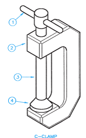
Assembly Drawings must have a number of views to show how parts fit together. Size 134kB from 10102011. FIGURE 1 CLAMP ASSEMBLY Catalog for WOODCO USA Brand Clamps for Clamp Hub Connections WOODCO USA presents this catalog to secure your business.
00605-008 - Toggle pliers double threaded screw version. Description Kant Twist Clamp design Download Kant Twist Clamp plans PDF and DWG AutoCAD. This video make by Vishwakarma Engineering Drawing Classes Bhilai Nagar.
Limiting dimension of the job are as follows. Assembly sheet metal fabrication woodworking auto repair etc. Clamping Capacity Throat Depth Clamping Force Approx.
Assembly Drawings must provide sufficient information to enable the assembly of a component. 1 5 Lock plate MS. Download the model according to the specified sizing parameters in either 3D or 2D format.
View C-Clamp Assembly Drawing 1of4 1pdf from ENGR 464 at San Francisco State University. C CLAMP ASSEMBLY all parts GIRRAJ SHARMA.

Assembly Drawing Of C Clamp Youtube
Assembly Drawing Of C Clamp Youtube

Assembly And Details
Assembly And Details
Working Drawing Metric Assembly Name C Clamp Specif Chegg Com

Assembly And Details
Working Drawing Metric Assembly Name C Clamp Specif Chegg Com

Autocad By Anthony Burke At Coroflot Com
0 comments
Post a Comment